Can we help you?
Contact us

Can we help you?
Contact us

Thank you for contacting us
Your form has been submitted successfully Our team will contact you again as soon as possible.
Whooppss...!! An error has occurred
Try sending later or write an email directly to areaempresas@ua.es

 PATENTED TECHNOLOGY
INFO
SHEET
DOWNLOAD
EXECUTIVE
ABSTRACT
CONTACT DETAILS: Research Results Transfer Office-OTRI
University of Alicante
Tel.: +34 96 590 99 59
Email: areaempresas@ua.es
http://innoua.ua.es
The present invention refers to a connection system of mixed concrete-wood structures formed by at least one connector comprising: a head that anchors the bolt to the concrete and which in turn consists of a clamping head and a body of larger diameter with the function of a distribution washer; and another body formed by a neck without thread, a threaded zone, and a self-drilling tip.
The dimensions of the elements comprising this invention will be determined by the characteristics of the structures they connect.
The main innovation of this invention is that the dimensions of the washer prevent the concrete from being crushed and, therefore, prematurely depleted. In addition, it is very easy to assemble the connection system, which has a high strength, transmits the stresses between the concrete slab and the wood structure efficiently and increases the flexural strength characteristics.
The system for the connection of mixed concrete and wood structures developed is useful for the rehabilitation of structures involving wooden beams supporting a concrete slab, as well as for new constructions such as framing, slabs, footbridges and bridges.
Companies interested in acquiring this technology for commercial exploitation are sought.
The interest in mixed concrete and wood structures is fully justified by their technical application in the rehabilitation of old wood floor slabs, in new floor slabs or in any other structural typology under the protection, among others, of environmental and sustainability criteria, since wood is a material with lower energy costs than classic concrete or steel.
In this type of structure, the connection between materials is what makes possible the joint work of all of them, being at the same time a critical point. That is why there are many connections in mixed concrete and wood structures (most of them based on metallic elements) and others that also include systems for their placement.
The problem with some of these connections is that the elements tested are exhausted (this is what is known as breaking mode) by local crushing of the concrete around the base of the connector because it works primarily with shear or bending and generally mobilizes little concrete in the concrete-connector contact. This is the case with bolt type connectors. In other cases, they are broken by the removal of a concrete cone, and in other cases, the breakage is caused by the tearing of the wood due to the thread of the screw or the sliding of a toothed plate.
There is therefore a need to provide a system that is stronger, has a high rigidity of connection, avoids certain modes of breakage and is more efficient than the systems described in the state of the art of the corresponding patent.
The Department of Civil Engineering of the University of Alicante has developed a screw type system for the connection of mixed concrete and wood structures, which includes (Figure 1):
• a head configured to anchor the lag bolt to the concrete, which is made up of:
> a clamping head that may be square, hexagonal or ALLEN-shaped (Figure 2), and
> at least one larger diameter washer-shaped body of suitable thickness. It can be forged in the same body or a captive washer next to the head.
• a body comprising:
> an unthreaded neck,
> a threaded area,
> a self-drilling tip

The washer body has a diameter 4 to 8 times larger than the diameter of the neck in order to transmit stresses to a sufficiently large area to avoid crushing the concrete. The thickness of the washer is 0.5 to 0.6 times the diameter of the neck, sufficient to withstand the shear and bending stresses that occur on it at the height of its support on the general body. The diameter and thickness of the washer will vary depending on the strength of the metal material and the concrete and must be designed accordingly to prevent crushing of the concrete.
The threaded area, which must penetrate into the wood, must be long enough for the lag bolt to break before it is pulled out of the wood. The type of thread is essential to avoid the need for longer lengths. The thread used is the natural wood thread DIN:7998.
The tip of the lag bolt is self-drilling so that it penetrates into the wood without the need for prior guidance. For diameters greater than 8-10 mm, depending on the quality and dimensions of the wood, a pre-drill may be required. This may be necessary for structures requiring large diameter connectors (e.g., bridges).
The lag screws are positioned at an angle (α) to the 45º contact plane (Figure 3). In this way, it is possible to work with traction (and to a lesser extent, flexion) as a priority. The connector was threaded into the wood using the appropriate instruments on the chosen head with the help of a guide to ensure its placement and tilting.
The orientation of the inclination of the lag bolts shall be changed according to the loads supported in order to ensure that the slip force always makes it work with flexotraction. For example, in the case of beams or floor slabs designed for point loads, the point of application of the load is the point that marks the change in the orientation of the inclination of the lag bolts, whose separation will be generally constant (Figure 3). In the case of beams designed for distributed loads, on the other hand, the center of gravity of the distributed load shall be the center of gravity of the tilt change, the spacing of which shall be generally variable.
Preferably, the lag bolt is in the plane of symmetry of the wooden beam, although it may also not be in the plane of symmetry of the beam and may be placed alternately at a certain distance from it.
The separation between the lag bolts will depend on the loads to which the mixed structure is subjected, the materials, areas and inertias of the section of each bolt, the inclination and rigidity provided by the connection, among other characteristics.
The connection system is installed with the help of a shoring system according to the usual construction technique for mixed structures that supports the concrete slab during its setting, or a recoverable formwork is fixed to the wooden beams (Figure 4). In assembly A, the formwork is supported by slats which are screwed to the wooden beams as supporting elements and supported in the centre of the span. In assembly B, the wooden beams are not used as load-bearing elements and the entire formwork has to be supported directly.

The present invention solves the problems of the state of the art since:
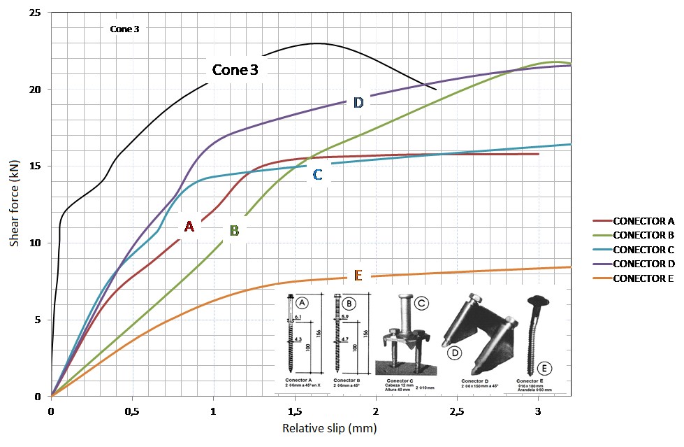
• It provides a system of connection between the wood and the concrete that acts as a mixed structure of resistance and rigidity superior to those obtained with other types of connectors (Figure 5).
• It avoids overall breakage due to local crushing of concrete around the washer body and avoids breakage due to tearing of the wood.

Another advantage is the compressive stress between the two materials, due to the inclined arrangement of the lag bolts, which increases friction between them and favours the good behaviour of the whole.
In addition, as no special tools are required for installation, it is very easy to install the connection system.
INNOVATIVE ASPECTS
The main innovative aspect of this invention is that the diameter of the washer body, being much larger than the rest, transmits stresses to a sufficiently large area, thus avoiding the crushing of the concrete, and therefore a premature exhaustion.
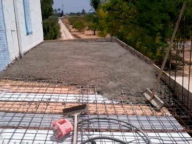
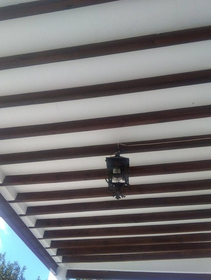
The technology has been developed on a laboratory scale in terms of the connection system itself (Figure 6), and full-scale prototypes (Figure 7) have been tested until breakage. It has also been successfully applied in the rehabilitation of a real case of old slab with wooden beams (Figures 8.a, 8.b and 8.c).
Figure 6. Connection test piece during and after breakage.
Figure 7. Full scale prototype, 5.40 m long.

Figure 8.a. Rehabilitation. Beams with connectors.

.
Figure 8.b. Rehabilitation. Concreting of the floor slab.

Figure 8.c. Rehabilitation completed, bottom view.
The present invention falls within the general field of metal fasteners for wood and, in particular, refers to a system for connecting mixed concrete and wood structures and their use for the rehabilitation of structures involving wooden beams that support a concrete slab, or for new buildings of the same materials, either with sawn or laminated wood, in the latter case achieving the mastery of large spans.
We are looking for companies that manufacture screws and wood structure construction sector interested in acquiring this technology for commercial exploitation through:
• Patent licensing agreements to assign the rights of use, manufacture or marketing of the technology to third parties.
• R&D (technical cooperation) project agreements for the use of technology.
• Subcontracting agreements for technical assistance, training, etc.
This technology is protected by granted patent.
• Title of the patent: "Sistema de conexión de estructuras mixtas de hormigón y madera".
• Application number: 201630797
• Application date: 10/06/2016
Carretera San Vicente del Raspeig s/n - 03690 San Vicente del Raspeig - Alicante
Tel.: (+34) 965 90 9959


